Restrict Flow’s Anti-Cavitate Orifice Plate™ is a single-stage cavitation control orifice plate for liquid piping systems where a standard restriction orifice plate may create damaging downstream cavitation. This fixed-geometry pressure-reduction device is engineered to manage pressure drop and cavitation within the plate while fitting between standard flanges.
Cavitation is a system-level problem driven by pressure drop and energy dissipation within piping systems.
Cavitation in liquid flow: cavitating vs. Anti-Cavitate Orifice Plate™
© 2026 Restrict Flow L.L.C.| restrictflow.com .
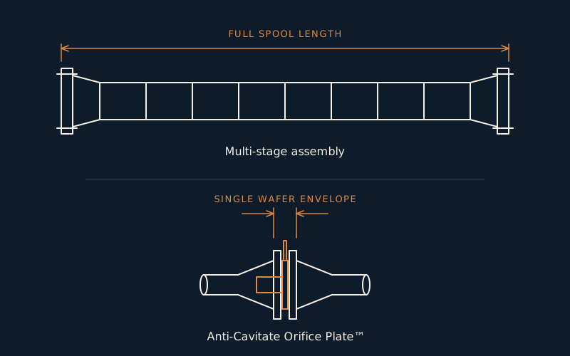
Restrict Flow’s Anti-Cavitate Orifice Plate™ can often replace a larger multi-stage assembly while managing the required pressure drop within a compact, single-stage device.
Power piping and process piping. Engineered to your service conditions. Stamped identification on the plate handle upon request.
Service-Disabled Veteran-Owned Small Business. Eligible for federal set-aside contracts.
Installs like a standard orifice plate within a compact flange-to-flange envelope.
Single-piece body engineered from the metallurgy the service environment requires.
Restrict Flow’s Anti-Cavitate Orifice Plate™ is engineered for liquid applications where a standard restriction orifice plate may create damaging downstream cavitation. Its single-stage flow path manages pressure drop and cavitation within the device, helping reduce damaging vapor collapse in downstream piping.
Each Anti-Cavitate Orifice Plate™ is designed from the operating conditions provided, including flow rate, pressure drop, pipe size, fluid properties, and temperature.
Design flow in GPM establishes the velocity and energy the plate must dissipate.
The differential across the plate defines the pressure recovery profile and cavitation risk.
Bore geometry and the available envelope are set by line size and wall schedule.
Fluid properties and vapor pressure govern where flashing or cavitation would occur.
The Anti-Cavitate Orifice Plate™ is engineered to manage cavitation and pressure reduction within the plate rather than allowing damaging vapor collapse to occur downstream in the piping. It installs between two standard flanges within a compact flange-to-flange envelope, allowing it to fit existing piping layouts without major modification.
Each plate is fabricated from a single piece of material and can be engineered from virtually any metallurgy the application requires. The result is a robust, application-specific flow element with no moving parts and no internal assemblies.
Where high pressure drops have traditionally been handled with multi-stage orifice plates, the Anti-Cavitate Orifice Plate™ achieves the required reduction in a single stage through engineered three-dimensional geometry.
The internal design is proprietary and not publicly disclosed. Each unit is custom engineered, and design details are protected to maintain performance reliability.
Inspection and maintenance requirements are simpler than many multi-stage designs. Multi-stage assemblies remain a traditional approach to high pressure drop, but their additional stages and larger assemblies can increase inspection and maintenance requirements compared with a single engineered plate.
The result is a simpler inspection profile compared with larger multi-stage assemblies.
Each unit is engineered per application. The configuration shown is a representative design case only. Actual designs vary with project-specific data.
Sample configuration. Actual flange spacing and installation requirements depend on the final engineered design, flange arrangement, and project conditions.
The internal design of the Anti-Cavitate Orifice Plate™ is proprietary and not publicly disclosed. The spec sheet shows how the plate fits within existing piping envelopes and achieves the targeted pressure drop for one engineered case.