
On the discharge side of a pump, cavitation is usually caused by a local pressure drop rather than low pressure throughout the system. Restrictions, valves, fittings, and changes in flow area can accelerate the liquid enough to lower local static pressure below vapor pressure.
A restriction orifice plate is one common location where this can occur when a large pressure drop is taken across a single restriction. The same mechanism can occur elsewhere in water systems where pressure is reduced rapidly.
Restrict Flow evaluates pump discharge cavitation from the actual operating conditions, including flow rate, upstream and downstream pressure, fluid temperature, pipe size, and restriction geometry.
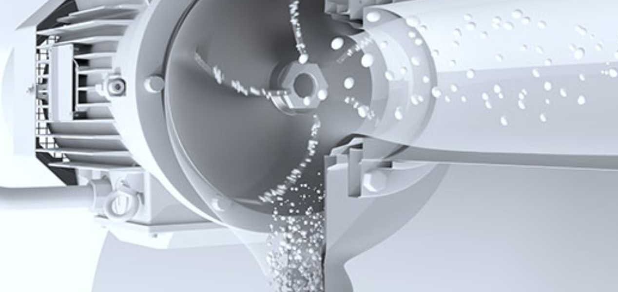
What is pump discharge cavitation?
Pump discharge cavitation occurs when local pressure somewhere downstream of the pump falls below the liquid’s vapor pressure. Vapor bubbles form in that low-pressure region and collapse when pressure recovers.
Repeated bubble collapse can cause noise, vibration, pitting, erosion, and wear near restrictions or other areas of rapid pressure change. Although cavitation is often associated with pump suction and NPSH, it can also occur on the discharge side when local pressure conditions allow it.
Why cavitation happens after the pump
Pressure is generally higher after a pump, but local pressure can still fall sharply across a restriction. The key is not discharge pressure alone, but the minimum local pressure created as flow accelerates through the restriction.
Sudden pressure drop across a restriction
When flow is forced through an orifice plate, valve, or other restriction immediately downstream of the pump, local static pressure can drop rapidly in the restricted area. If that drop is significant enough, it can fall below vapor pressure.
High flow velocity
Pumps operating at higher flow rates increase velocity in the discharge line. Higher velocity contributes to lower static pressure, particularly at restriction points.
Concentrated pressure reduction
If most of the system's pressure drop is handled at a single location rather than distributed more gradually, the likelihood of cavitation can increase.
Operation outside the pump curve
When a pump operates away from its best efficiency point, flow conditions can become less stable. This can contribute to uneven pressure distribution and increase the risk of cavitation.
Common signs of cavitation in discharge lines
In operating systems, cavitation rarely announces itself clearly. Instead, it tends to show up through indirect symptoms:
- Persistent or increasing vibration in downstream piping
- Noise described as "gravel," "crackling," or "popping"
- Premature wear or pitting in valves, piping, or fittings
- Reduced reliability of downstream components
- Maintenance issues that seem to repeat without a clear cause
Because these symptoms can overlap with mechanical problems, cavitation is often misdiagnosed or overlooked.
Where it typically occurs
Pump discharge cavitation is most often found in areas where flow conditions change rapidly:
- At restrictions or fittings downstream of the pump
- Across orifice plates or restriction devices
- At control valves operating with high pressure differentials
- In piping with multiple elbows or directional changes
- At discharge points into lower-pressure systems
These are all locations where pressure, velocity, and turbulence interact.
Common mistakes in pump discharge design
Looking across different systems, a few patterns show up consistently:
- Handling too much pressure drop at a single restriction point
- Placing restriction devices too close to the pump discharge
- Ignoring the effect of velocity on localized pressure
- Assuming that discharge-side pressure removes cavitation risk
- Treating vibration and noise as normal operating conditions
None of these decisions are unusual on their own, but together they create the conditions where cavitation develops.
A more practical approach to control
Controlling pump discharge cavitation requires managing how pressure is reduced after the pump. Large, concentrated pressure drops can create low-pressure regions where vapor forms and later collapses as pressure recovers.
Manage how pressure is reduced
Avoid sudden, concentrated pressure drops, reduce turbulence at restriction points, manage velocity through critical sections of piping, and distribute pressure reduction more evenly. In many cases this can be addressed with properly designed restriction devices that control how energy is dissipated in the fluid, rather than simply restricting flow.
For severe cavitation risk, the Anti-Cavitate Orifice Plate™ can be evaluated as one option for managing pressure drop and cavitation behavior.
Manage cavitation at the restriction
Restrict Flow’s Anti-Cavitate Orifice Plate™ is designed to manage pressure drop and cavitation within a single-stage device, helping reduce damaging vapor collapse in downstream piping.
What improves when cavitation is addressed
When cavitation is reduced in a discharge system, the improvements are typically noticeable:
- Lower vibration levels in piping and supports
- Reduced noise during operation
- Slower rates of material wear
- Improved reliability of downstream components
- Fewer unplanned maintenance events
For maintenance teams, this often means fewer recurring issues and more predictable operation.
Final thoughts
Cavitation in pump discharge lines is not unusual, but it is often misunderstood. The key factor is not the presence of pressure, but how that pressure is reduced as flow moves through the system. When pressure drop is managed more effectively, the conditions that contribute to cavitation can often be reduced.
For engineers and operators working with high-flow water systems, taking a closer look at discharge-side conditions can often explain issues that might otherwise be attributed to mechanical problems.

