Cavitation can occur anywhere a piping system creates a rapid pressure reduction, including across restriction orifice plates, control valves, and other flow restrictions. Although cavitation is often associated with pumps, the damaging vapor-bubble collapse may occur farther downstream as pressure begins to recover.
Restrict Flow evaluates cavitation as a pressure-management problem within the piping system, considering the relationship between pressure drop, fluid vapor pressure, velocity, temperature, and restriction geometry. These conditions are especially important in applications such as boiler blowdown, pump discharge, and other high-pressure-drop liquid services.
What causes cavitation in piping systems?
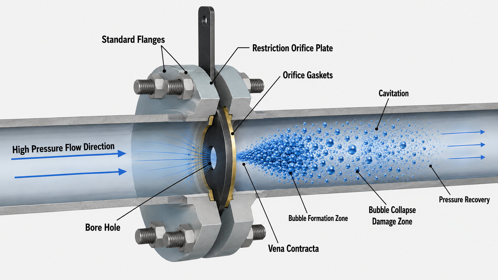
Cavitation is governed by the relationship between pressure, velocity, and fluid properties. As fluid passes through a restriction, velocity increases while static pressure decreases. At the point of maximum velocity, commonly referred to as the vena contracta, pressure can drop below the liquid's vapor pressure, causing the fluid to partially vaporize and form bubbles.
As the fluid moves downstream and pressure recovers, these vapor bubbles collapse rapidly. This collapse produces micro-jets and shockwaves that impact surrounding surfaces. With a standard restriction orifice plate, this pressure drop and recovery can produce damaging orifice plate cavitation as vapor bubbles collapse downstream of the plate.
Key factors that influence cavitation include:
- Flow rate
- Fluid temperature
- Pressure differential
- Restriction geometry
Understanding how variables such as flow rate and fluid temperature affect cavitation is critical when designing any restriction system.
For further reading, see our Pumps & Systems article summary on cavitation in piping systems.
Where does cavitation occur?
Cavitation most often occurs where high-pressure liquid is forced through a restriction followed by rapid pressure recovery. These conditions create localized low-pressure zones where vapor bubbles form and collapse.
Signs of cavitation in piping systems
Cavitation can often be identified by consistent physical and operational indicators:
- A distinct "gravel" or "marbles" sound in the line
- Excessive vibration in piping
- Fluctuating pressure readings
- Reduced system performance
- Premature equipment wear
Recognizing these signs early can reduce the risk of significant damage and downtime.
Cavitation damage and its impact
The collapse of vapor bubbles generates extremely high localized forces. Over time, this leads to:
- Surface pitting and erosion
- Valve and fitting degradation
- Pipe wall thinning
- Increased maintenance costs
- Potential system failure
This type of cavitation damage is cumulative and accelerates if left unaddressed. It is commonly observed in high-energy systems such as pump discharge and boiler blowdown applications.
Cavitation vs flashing: key differences
Cavitation is often confused with flashing, but the two phenomena behave very differently. Cavitation involves vapor bubble formation followed by collapse, while flashing occurs when vapor forms and does not collapse. The difference determines how and where system damage occurs.
Read the full comparison: cavitation vs flashing in piping systems.
Why traditional cavitation approaches have limits
Traditional cavitation-control methods include specialized control valves, multi-stage pressure reduction systems, and other engineered approaches that manage pressure and velocity through the system. Multi-stage designs distribute the total pressure drop across multiple restrictions to reduce the severity of the pressure change at each stage.
These approaches can be effective, but they may require additional installation length, multiple restriction stages, and greater system complexity. For applications where installation space or simplicity is important, a single-stage engineered flow path may provide another method of controlling where cavitation forms and collapses.
Cavitation control methods
Effective cavitation control requires managing how pressure and velocity change throughout the system. When these variables are not properly managed, localized pressure drops can lead to vapor formation and collapse within the piping. Key strategies include:
- Managing pressure drop across restrictions
- Controlling velocity profiles
- Distributing energy dissipation
- Controlling pressure recovery
While these approaches can reduce the severity of cavitation, they often do not address the root cause, especially in high-energy systems such as pump discharge and boiler blowdown applications.
Control where cavitation forms and collapses
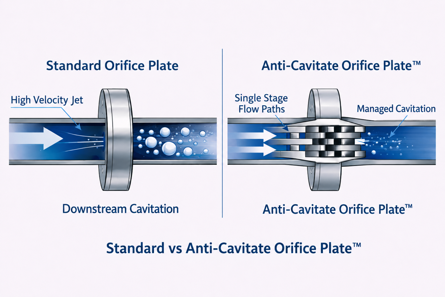
Another approach is to control where cavitation forms and where vapor collapse occurs. Restrict Flow's Anti-Cavitate Orifice Plate™ is designed to manage pressure drop and energy dissipation within the restriction itself, helping mitigate damaging vapor collapse in downstream piping. This shifts cavitation from an uncontrolled downstream event toward a controlled condition within the device.
Engineered cavitation control in piping systems
Rather than attempting to eliminate cavitation entirely, modern engineering solutions focus on controlling where and how it occurs.
In both pump discharge and boiler blowdown systems, the root issue is not the presence of cavitation, but where it is allowed to collapse within the system. This shift, from trying to eliminate cavitation to controlling where it occurs, is fundamental to modern cavitation mitigation.
Cavitation control at the point of restriction
Unlike approaches that manage cavitation downstream, the Anti-Cavitate Orifice Plate™ is designed to contain cavitation within the device, dissipate energy internally, and help protect downstream piping, in a single fixed-geometry device.
Industrial applications of cavitation control
Cavitation is a widespread issue across high-pressure liquid systems, including power generation, water infrastructure, chemical processing, and marine applications. Each industry presents unique operating conditions, but the underlying mechanisms remain consistent. Explore how cavitation affects different sectors.
Controlling cavitation at the source
Cavitation in piping systems is a predictable and manageable engineering challenge when properly understood. If your system is experiencing noise, vibration, or premature wear, cavitation may already be present. Evaluating pressure drop, flow conditions, and system geometry is critical to selecting the correct solution.

