What causes cavitation?
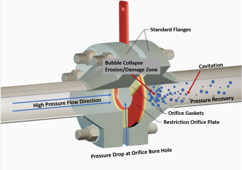
Cavitation occurs when the local pressure in a flowing liquid drops below the liquid’s vapor pressure, causing vapor bubbles to form. When pressure recovers downstream, those bubbles collapse and can create noise, vibration, erosion, and damage to piping, valves, pumps, and restriction devices.
Water-system cavitation is usually caused by a combination of flow rate, pressure reduction, temperature, and piping geometry. Pumps, valves, restrictions, elbows, and other changes in flow area can create local low-pressure zones even when overall system pressure appears adequate.
Restrict Flow evaluates these applications using the actual operating conditions, including flow rate, upstream and downstream pressure, water temperature, pipe size, and restriction geometry.
This page explains where cavitation develops in water systems, what the damage looks like, and how pressure reduction can be managed to reduce damaging vapor collapse.
What cavitation looks like in practice
Cavitation begins when local pressure falls below the water’s vapor pressure and vapor bubbles form. As the water moves into a higher-pressure region, those bubbles collapse, producing localized forces that can pit metal surfaces, create vibration, and generate audible noise.
In operating systems, cavitation is often caused by several conditions acting together:
- A pump pushing higher velocity than originally intended
- A restriction creating a sudden pressure drop
- Geometry changes such as elbows and tees amplifying turbulence
- Rapid pressure recovery downstream of a restriction
Each of these by itself may be acceptable. Together, they create the conditions where cavitation becomes sustained and destructive.
Where cavitation typically occurs
In water systems, cavitation tends to show up in predictable locations, usually areas where pressure and velocity are changing at the same time.
Pump discharge lines
One of the most common locations. High velocity leaving the pump combined with downstream restriction creates a rapid pressure drop. If that drop is not controlled, cavitation can form downstream. This is discussed further under pump discharge cavitation. For groundwater applications, see our guidance on pressure reduction for water wells.
Boiler water lines
Boiler feedwater and blowdown systems operate under different conditions, but both may involve large pressure differentials. Blowdown service is especially susceptible when hot water undergoes rapid pressure reduction. See boiler blowdown cavitation for blowdown-specific conditions.
Flow restriction points
Orifice plates, control valves, and other restriction devices are common locations where cavitation can develop. The issue is not the presence of restriction, but how the pressure drop is handled across it.
Pressure-reduction stations
Control valves, orifice plates, and other restriction devices used to reduce water pressure can create local low-pressure zones when a large pressure drop is concentrated at one location. For building water applications, see our guidance on cavitation control for commercial systems.
Marine and seawater systems
Space constraints and continuous operation make these systems particularly sensitive. Cavitation often develops in cooling loops and onboard distribution systems where pressure control is limited.
Why cavitation gets missed
One reason cavitation persists in operating systems is that it rarely causes immediate failure. Early signs tend to be subtle:
- Increased noise near a restriction
- Low-level vibration
- Slight performance degradation
Because these changes can be gradual, they are often attributed to normal system behavior. Maintenance teams may notice wear over time but not always connect it directly to cavitation. By the time the issue is clearly identified, through pitting, erosion, or repeated component failure, the system has likely been operating in a cavitating condition for an extended period.
What damage cavitation actually causes
The effects of cavitation are cumulative. It is not a one-time event but a repeated stress on the system. Common impacts include:
- Material erosion. Collapsing bubbles create localized impact forces that remove material over time, showing up as pitting, often in specific zones rather than uniform wear.
- Vibration. Irregular flow behavior translates into vibration that can affect the immediate component as well as supports and adjacent piping.
- Noise. The "crackling" or "gravel" sound is one of the more recognizable indicators and a sign that damage may already be occurring.
- Reduced equipment life. Valves, piping, and downstream equipment all see reduced lifespan under sustained cavitation.
- Increased maintenance. More frequent inspections, repairs, and replacements become necessary, often without a clear root cause being identified.
Traditional approaches and their tradeoffs
Common approaches to water-system cavitation include multi-stage restriction orifice assemblies, control valves, and piping modifications. When properly engineered, these methods can reduce cavitation severity by managing how pressure changes through the system.
Depending on the application, they may require additional installation space, components, maintenance access, or piping changes. These requirements can be difficult to accommodate in existing systems.
A more practical way to think about it
Start by identifying where pressure reaches its minimum and where it recovers. Cavitation risk increases when local pressure falls below vapor pressure and the resulting bubbles collapse farther downstream.
Control how pressure drop occurs
Avoid sharp, concentrated pressure drops, reduce turbulence at restriction points, and maintain more stable flow conditions. In practice, this often leads to simpler solutions that focus on how energy is dissipated in the fluid, rather than just adding more components.
One example is using a properly designed restriction device that manages pressure drop in a controlled way while minimizing turbulence. When applied correctly, this type of approach can often reduce cavitation without requiring major system changes.
Manage cavitation at the restriction
For water systems with severe cavitation risk, Restrict Flow’s Anti-Cavitate Orifice Plate™ is designed to manage pressure drop and cavitation within a single-stage device, helping reduce damaging vapor collapse in downstream piping.
Common mistakes in system design and operation
Looking across different applications, a few patterns show up repeatedly:
- System operation occurring outside of the pump curve
- Ignoring velocity effects downstream of pumps
- Assuming noise and vibration are normal
- Adding complexity instead of addressing flow behavior
None of these are unusual, but they contribute directly to cavitation conditions.
What improves when cavitation is addressed
When cavitation is reduced, the improvements tend to be noticeable:
- Lower noise levels
- Reduced vibration
- Slower material degradation
- More predictable system behavior
- Fewer unplanned maintenance events
For operations and maintenance teams, that usually means less time reacting to issues and more time running the system as intended.
Final thoughts
Cavitation in water systems is not always avoidable, but in many cases it is manageable with a closer look at how pressure and flow are being handled. Most of the time, the issue comes down to how pressure drop is introduced into the system. When that is controlled more effectively, the conditions that contribute to cavitation can often be reduced.
For engineers and operators working with high-volume water systems, addressing cavitation is less about adding complexity and more about understanding how the fluid is behaving under real operating conditions.

