
Single-Stage vs Multi-Stage Orifice Plates — Which Is Right for Your System
- May 18
- 6 min read
Single-Stage vs Multi-Stage Orifice Plates — Which Is Right for Your System
A 6-inch Schedule 80 water injection line operating at 450 psig upstream pressure with a downstream delivery requirement of 35 psig presents a pressure reduction demand that a single sharp-edged orifice plate may not be suitable without a cavitation review. The fluid accelerates through the orifice bore, static pressure at the vena contracta drops below the local saturation threshold for the fluid at service temperature, and vapor bubbles form — only to collapse violently as pressure partially recovers downstream. What follows in uninstrumented systems is not always immediately obvious: material loss progresses at the downstream face of the plate and along the adjacent pipe wall before any process alarm triggers.
The mechanics behind this behavior are straightforward. As flow contracts through the orifice, kinetic energy rises sharply and static pressure falls. The minimum static-pressure point — the vena contracta — occurs slightly downstream of the physical restriction. In high differential-pressure services, the gap between vena contracta pressure and fluid vapor pressure determines whether phase change occurs. When that margin closes, the collapse zone forms immediately downstream of the bore exit. The implosion energy from bubble collapse is localized, repetitive, and directional, making pipe-wall perforation and orifice-plate erosion the characteristic failure modes in these services.
Where the Cavitation Index Becomes the Design Variable
The dimensionless cavitation index sigma (σ) quantifies the ratio of available pressure above vapor pressure to the applied differential pressure across a restriction. When σ drops below the incipient cavitation threshold for a given orifice geometry, phase change begins. For a broader explanation of how cavitation develops in liquid piping systems, see our cavitation overview. For sharp-edged orifices with beta ratios in the 0.3 to 0.5 range, incipient cavitation can initiate at σ values well above 1.0, depending on fluid temperature, dissolved gas content, and surface finish of the bore. Miller's Flow Measurement Engineering Handbook documents the relationship between beta ratio, discharge coefficient, and pressure distribution in ways that make the sigma calculation tractable for most piping engineers, but the handbook also makes clear that single-stage sharp-edged plates have a limited practical window in high-differential services.
At fluid temperatures approaching 200°F (93°C), vapor pressure rises meaningfully, which compresses the available margin between vena contracta pressure and the phase-change threshold. A service that runs without cavitation at 60°F may produce aggressive bubble collapse at the same differential pressure once seasonal or process temperature shifts occur. This is not a marginal effect — it changes the σ value enough to cross the incipient threshold entirely, converting what looked like a stable installation into one generating audible cavitation noise and measurable erosion over a single operating season.
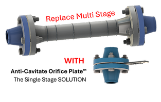
Multi-Stage Pressure Reduction: The Established Engineering Response
The conventional engineering response to high differential-pressure services has been to distribute the total pressure drop across multiple orifice plates installed in series. Each plate takes a fraction of the total drop, keeping the vena contracta pressure at each stage above the local saturation threshold. If the 415 psig drop from the injection line example is split across three plates, each stage handles roughly 138 psig, and the downstream hydraulic recovery between stages allows static pressure to restabilize before the next restriction is encountered. This approach is commonly used in refinery, chemical, water injection, and other process piping services where staged pressure reduction is needed. For more detail, see our multi-stage restriction orifice plate overview.
The engineering constraints of multi-stage installations are real and worth accounting for at the design stage. Each stage requires enough spacing or spool length to allow pressure recovery and hydraulic stabilization before the next restriction. In retrofit applications where existing pipe routing limits available straight run, achieving the necessary inter-stage stabilization distances can force rerouting or require expansion of the pipe rack envelope. Each weld joint added for a new spool introduces a pressure-test requirement, which carries outage time. There is also a cascade consideration: if one stage in a three-plate series is pulled for inspection and not reinstalled before the line is returned to service, the remaining two stages absorb the full differential pressure, and each one is now operating in a regime for which it was not sized. The downstream transition region after each remaining plate compresses accordingly, and cavitation damage can initiate within a single operating shift.
Single-Stage Controlled Dissipation: Managing the Hydraulic Transition Internally
A different engineering approach addresses the same problem by managing the internal pressure drop distribution within a single plate geometry rather than staging the drop across multiple discrete devices. The principle is that the vena contracta pressure — the critical quantity in cavitation onset — is a function not only of total differential pressure but of how that pressure drop is distributed across the flow path through the restriction. A plate geometry should be evaluated across the full operating range because changes in flow rate, upstream pressure, downstream pressure, and temperature can shift cavitation behavior.
The material selection for these plates matters significantly in high-differential services. 316L stainless steel is adequate for many water and process fluid applications, but in services with chloride exposure, elevated temperature, or aggressive chemical environments, duplex or super duplex alloys offer substantially better resistance to the combined erosion-corrosion mechanism that accelerates material loss in vapor-collapse locations. Some high-pressure hydrocarbon services have used Hastelloy C-276 plates where hydrogen sulfide partial pressure is a co-variable. The alloy selection should follow the fluid's corrosivity profile as rigorously as the hydraulic design — an orifice plate that manages cavitation thermodynamically but degrades through corrosion-assisted erosion has not solved the service problem.
Field Observations That Inform the Design Decision
During commissioning of a seawater lift system in an offshore platform application, a 4-inch Schedule 160 injection header with a 320 psig pressure drop across a single sharp-edged carbon steel orifice plate produced audible crackling within 48 hours of first flow. Inspection at the six-week mark showed cratering at the downstream plate face and measurable wall-thickness loss in the pipe segment immediately downstream of the plate. The downstream recompression behavior in that geometry was concentrating bubble-collapse energy against a 4-inch radius of pipe wall that had not been specified for erosion service. The plate and downstream spool were replaced with a multi-passage 316L plate, the acoustic signature did not return, and the subsequent six-month inspection showed no measurable wall loss. That field sequence is a concrete illustration of what the σ calculation predicts on paper: the original configuration was operating below the critical cavitation index for that fluid temperature and differential pressure.
The broader cavitation damage mechanism — including how vapor-collapse location shifts with changes in downstream back-pressure and flow rate — is a subject that warrants its own analysis when operating conditions are not tightly controlled. Systems where flow rate or upstream pressure varies seasonally or with process demand need their cavitation index evaluated across the full operating band, not just at design-point conditions. A plate geometry should be evaluated across the full operating range because changes in flow rate, upstream pressure, downstream pressure, and temperature can shift cavitation behavior.
Evaluating Your System Against These Parameters
The decision between a series multi-stage arrangement and a single-plate controlled-dissipation design is driven by the specifics of the service: total differential pressure, fluid temperature and vapor pressure at operating conditions, available straight run, inspection access, and whether the system will see variable flow demand. Neither architecture is universally applicable. A system with 80 psig of differential pressure at 60°F on clean water has no cavitation risk with a conventional orifice and no basis for a more complex solution. A system with 400 psig of differential at 180°F with limited straight run and no provision for intermediate spool inspection presents a different set of constraints entirely.
Engineers assessing a new installation or troubleshooting an existing one should start with the σ calculation at worst-case operating conditions — maximum differential pressure, maximum fluid temperature, minimum downstream back-pressure — and compare the result against the incipient cavitation threshold for the geometry under consideration. If the numbers place the system in or near the cavitation regime, the piping layout, material specification, and plate geometry all become active design variables rather than defaults. Submitting those system parameters — upstream and downstream pressures, fluid type and temperature, pipe size and schedule, and available spool length — for a hydraulic review is a practical first step toward a configuration that holds up across the full service life.
For applications involving high differential pressure, cavitation risk, or limited installation space, Restrict Flow can review the system data through the questionnaire form.


Comments